Carbon monoxide hazard: route the exhaust outdoors and never run the heater in an enclosed, unventilated space. A CO alarm is strongly recommended. Read the full safety information.
Video guides
H1
H1 Split installation guide
Installation video for the H1 split diesel air heater.
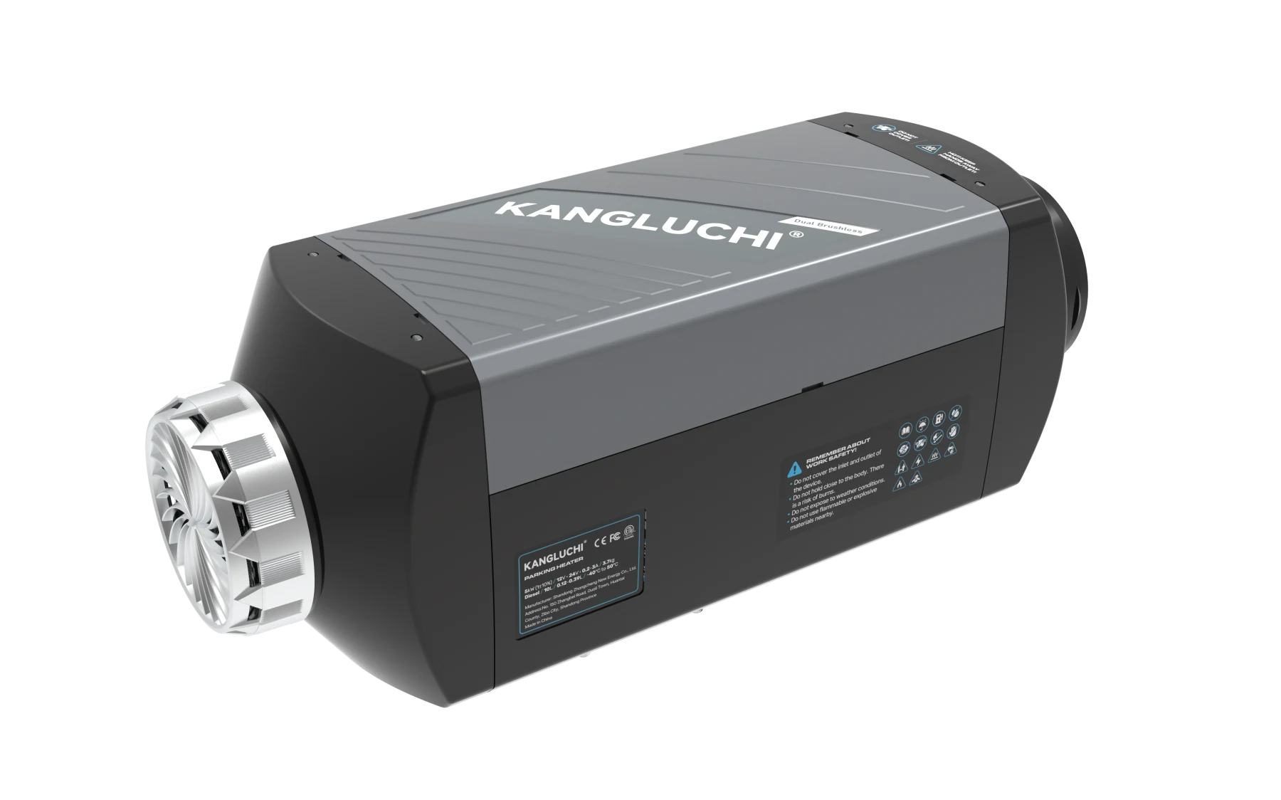
Read all instructions carefully before operating the heater. Actual product appearance may vary. Product specifications and software may be updated without prior notice.
Safety first
WARNING: Read all safety warnings, instructions, diagrams, and specifications. Failure to follow them may result in electric shock, fire, and/or serious personal injury. Avoid contact with toxic substances and take care to prevent fire from flammable materials.
Do not replace essential heater components, use other manufacturers’ replacement parts without authorization, or deviate from these instructions during installation or operation. Use only original accessories and replacement parts for installation and maintenance.
Do not use where flammable vapor or dust may be present, including fuel or coal storage facilities, lumber warehouses, granaries, and diesel/gasoline fueling stations. Keep the heater away from fuel tanks, compressor tanks, fire extinguishers, clothing, and other flammable items.
Do not start the heater with an open flame. Do not use it in an enclosed or unventilated area. Turn it off before refueling.
Do not disconnect power during operation or stop the heater by disconnecting power. If overtemperature protection stops heating, leave power connected and allow the unit to cool naturally and shut down before restarting.
After switching off, allow 3–5 minutes for shutdown cooling and a complete stop before disconnecting power. After starting, allow 3–5 minutes for normal operation and heat output.
If the fuel system leaks or sprays fuel, contact KANGLUCHI for service. Route the exhaust outdoors to prevent exhaust gases entering the occupied area.
Children aged 8 and over and people with reduced physical, sensory, or mental capabilities, or insufficient experience or knowledge, may use the appliance if supervised or instructed in safe use and they understand the hazards. Children must not play with it or clean or perform routine maintenance without adult supervision.
WARNING: Flammable Materials: Keep flammable materials away from the exhaust pipe during installation, use, maintenance, and disposal.
WARNING: Toxic Substances: During installation, use, maintenance, or disposal, provide adequate ventilation around the unit to prevent carbon monoxide poisoning. Route exhaust outdoors to prevent gases entering the enclosed area.
If the supplying fuel tank leaks, fuel must drain to the ground without contacting hot parts of the vehicle or load. A gasoline tank must have an effective flame arrester at the filler opening or a completely sealed closure.
Do not use where hazardous goods are loaded, unloaded, or transported. Use only for the intended purpose and be aware of injury from misuse. Install according to applicable regulations and use only in a well-ventilated area.
NOTICE: Use only the original power supply.
Continuous black smoke indicates carbon deposits in the combustion chamber, especially from the second year onward; remove them promptly. NOTICE: If any of the conditions above occurs, replace the air filter and fuel filter promptly.
A small amount of white smoke during initial use is normal: the unit is factory-tested and residual fuel undergoes secondary combustion.
NOTICE: The temperature sensor is built into the LCD control panel. Install the panel within the heated area or temperature control may operate incorrectly and cause abnormal heating.
The manual says this component is not an original accessory for a vehicle heater and does not meet the vehicle-heating technical requirements of ECE R122. This is a Class III appliance.
What’s in the box
Part
Quantity
LCD control panel
1
Remote control
1
Battery
2
Combustion air intake pipe
1
Exhaust pipe
1
Hot-air outlet duct
1
Air outlet
1
Air duct Y-connector
1
Air filter
1
Muffler
1
Muffler installation kit
1
Steel mounting plate (with gasket)
1
Rubber heat-insulating pad
1
Wiring harness
1
Fuel line + fuel metering pump assembly
1
Fuel tank
1
Fuel tank fittings
1
Air outlet duct clamp
2
Combustion air intake and exhaust pipe clamps
4
Nylon cable tie-5×250
5
Nylon cable tie-3×150
5
R-type clamp
2
Fuel line clamp
6
Self-drilling screw
6
Double-ended stud
4
M6 mounting nut
5
M6×30 mounting bolt
1
150 mm fuel line
1
M5×20 hex bolt
2
M5 hex nut
2
Hole saw
1
User Manual
1
Specifications
Specification
PDF value
Heating Medium
Air
Operating Voltage
12-24 V DC
Rated Heat Output
5 kW (±10%)
Rated Power
2.4-53 W
Fuel Consumption
0.12-0.39 L/h
Fuel
Diesel
Fuel Tank Capacity
10 L
Operating Temperature
-40 to 40 °C
Operating Noise
≤75 dB
Dimensions
386 × 144 × 173 mm
Installation
Have a qualified professional install this equipment. Use high-quality diesel, not kerosene, vegetable oil, gasoline, waste oil, or other fuels: these may cause odors or malfunction.
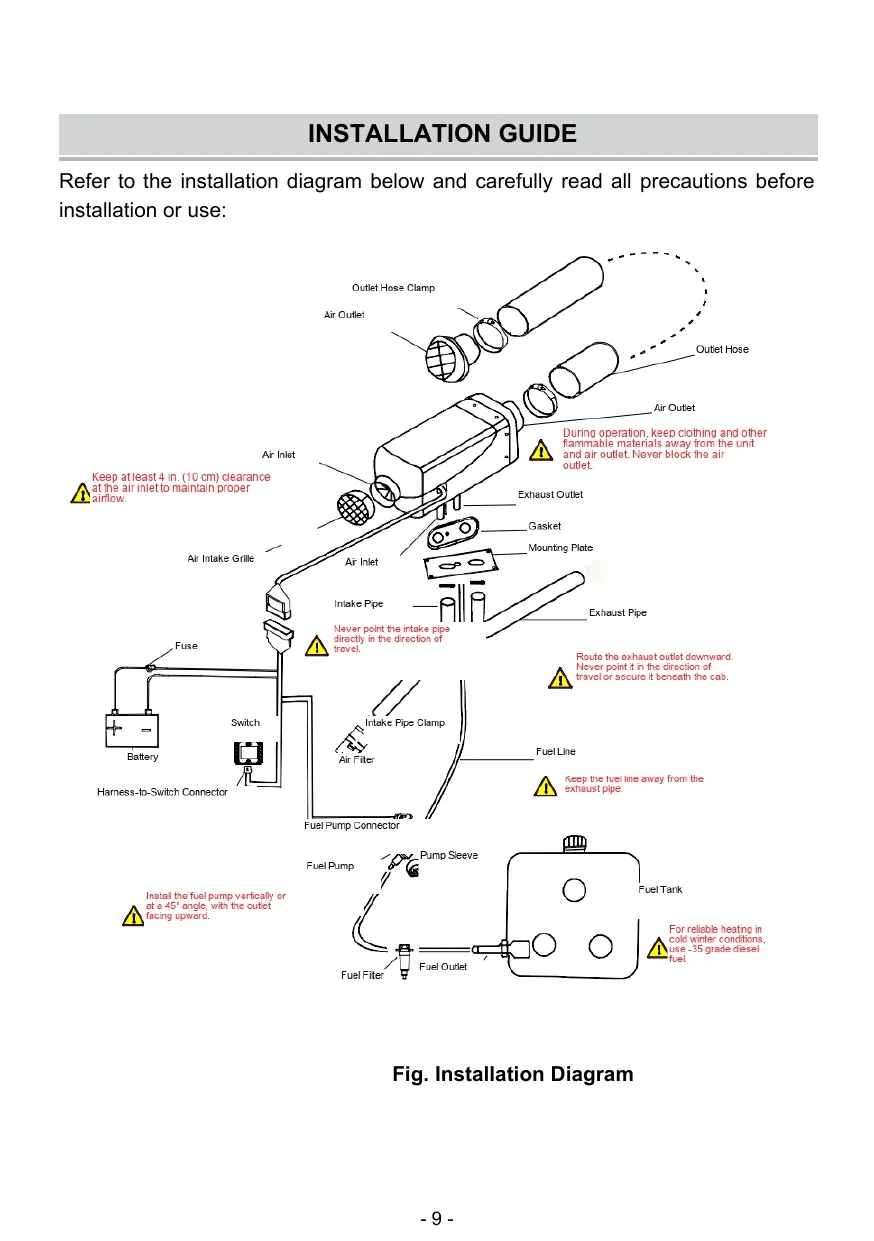
Review the installation diagram and precautions. Installation Diagram (manual p.9)
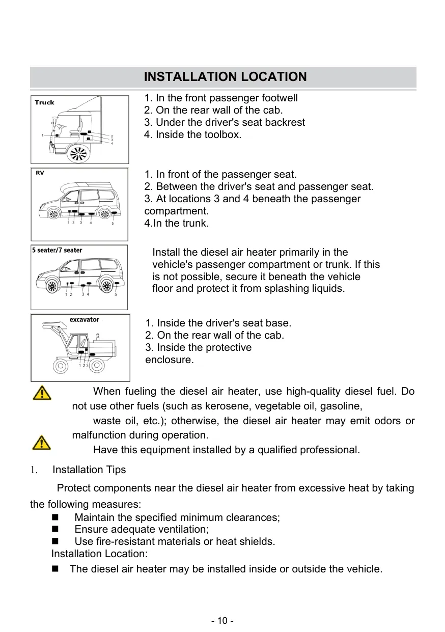
Choose a location. Examples shown include the front passenger footwell, rear cab wall, under the driver’s seat backrest, toolbox, in front of or between the seats, beneath the passenger compartment, trunk, driver’s seat base, and protective enclosure. Install primarily in the passenger compartment or trunk; if impossible, secure beneath the vehicle floor and protect from splashing liquids. The heater may be installed inside or outside the vehicle. Installation Locations (manual p.10)
Protect nearby components from heat with specified minimum clearances, ventilation, and fire-resistant materials or heat shields. Protect the heater from mechanical impact and other damage. If within the driver’s reach during normal operation, install a guard. If outside, protect from splashing water. Prevent water entering when passing through water up to the permitted fording depth.
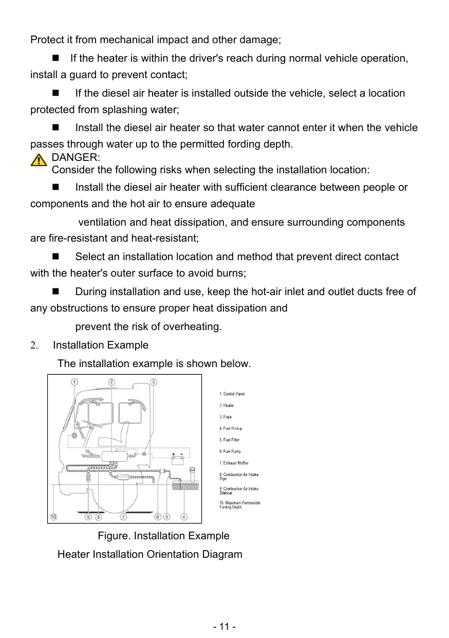
DANGER: Provide enough clearance between people or components and hot air for ventilation and heat dissipation; surrounding components must be fire- and heat-resistant. Prevent direct contact with the heater’s outer surface to avoid burns. Keep hot-air inlet and outlet ducts unobstructed during installation and use to prevent overheating. Installation Example (manual p.11)Heater Installation Orientation (manual p.12; p.11 shown above)
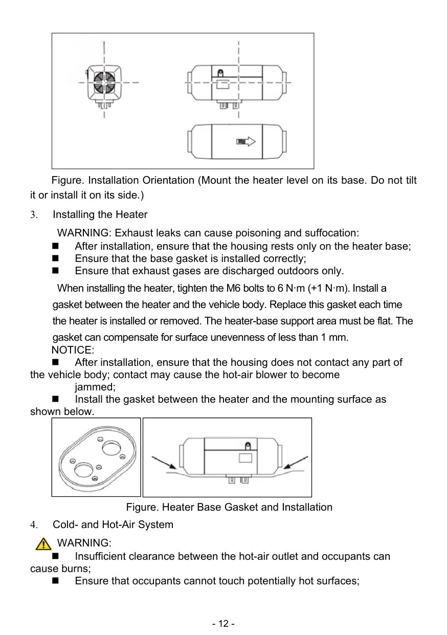
Mount the heater level on its base, not tilted or on its side. WARNING: Exhaust leaks can cause poisoning and suffocation: ensure the housing rests only on the heater base, the base gasket is correctly installed, and exhaust is discharged outdoors only. Tighten M6 bolts to 6 N·m (+1 N·m). Place a gasket between heater and vehicle body; replace it each time the heater is installed or removed. The support area must be flat; the gasket compensates for unevenness under 1 mm. NOTICE: The housing must not contact the vehicle body, which could jam the hot-air blower. See manual p.12 above.
WARNING: Keep sufficient clearance between hot-air outlet and occupants; prevent contact with hot surfaces and direct exposure to the hot-air stream. Draw cold intake air from a clean area so combustion exhaust cannot enter it. NOTE: Keep inlet-to-outlet duct pressure loss below 2 hPa or heating output will fall. Do not integrate with the vehicle air system or connect to an externally controlled distribution system such as the vehicle air conditioner. Temperature control: The heater adjusts output to heating demand, according to the room-temperature sensor and control-panel target.
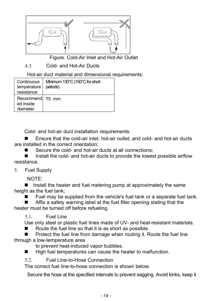
Keep inlets and outlets clean and free of debris. For the hot-air intake, do not draw from the vehicle heating system or heater exhaust; select a position protected from splashing and spray, above the vehicle’s maximum permitted wading depth. Keep heat-sensitive components out of the hot-air stream. After installation, check whether the cold air entering through the vehicle heater is too hot and prevent hot-air outlet flow recirculating directly into the cold-air inlet. Cold-Air Inlet and Hot-Air Outlet (manual p.14)
Use ducts rated for continuous temperatures of at least 130°C (150°C for short periods); recommended inside diameter is 75 mm. Orient cold- and hot-air ducts correctly, secure all connections, and minimize airflow resistance.
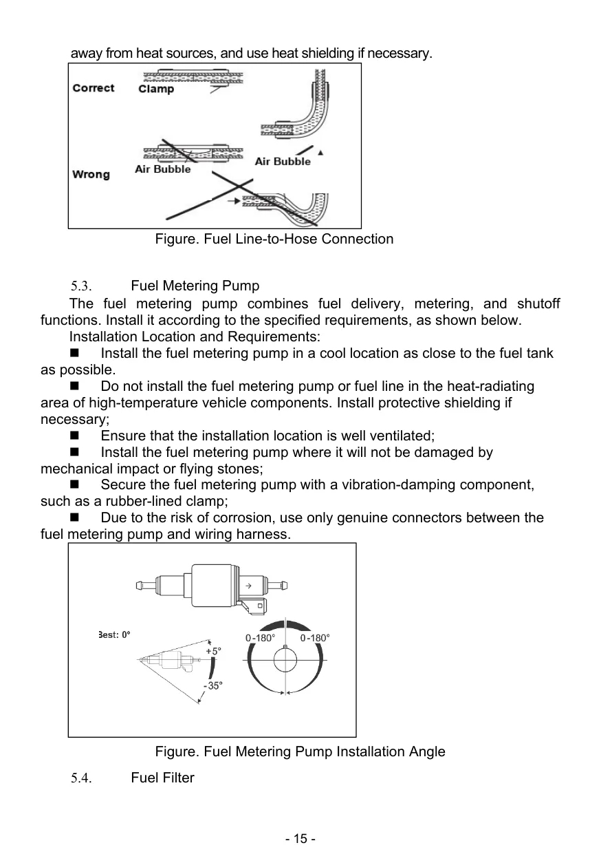
Install the heater and fuel metering pump at approximately the same height as the fuel tank. Fuel may come from the vehicle tank or a separate tank. Affix a warning at the filler opening to turn off the heater before refueling. Use only UV- and heat-resistant steel or plastic fuel lines; keep the line as short as possible, protect it from damage, and route through a low-temperature area to prevent vapor bubbles. High fuel temperatures can cause malfunction. Secure hose connections at the specified intervals to prevent sagging, avoid kinks, keep away from heat, and shield if necessary. Fuel Line-to-Hose Connection (manual p.15)
Install the fuel metering pump in a cool, well-ventilated location as close as possible to the tank, protected from impact and flying stones. Do not place pump or line in the heat-radiating area of hot vehicle components; shield if necessary. Secure the pump with a vibration-damping component such as a rubber-lined clamp. Use only genuine connectors between pump and harness because of corrosion risk. See manual p.15 above.
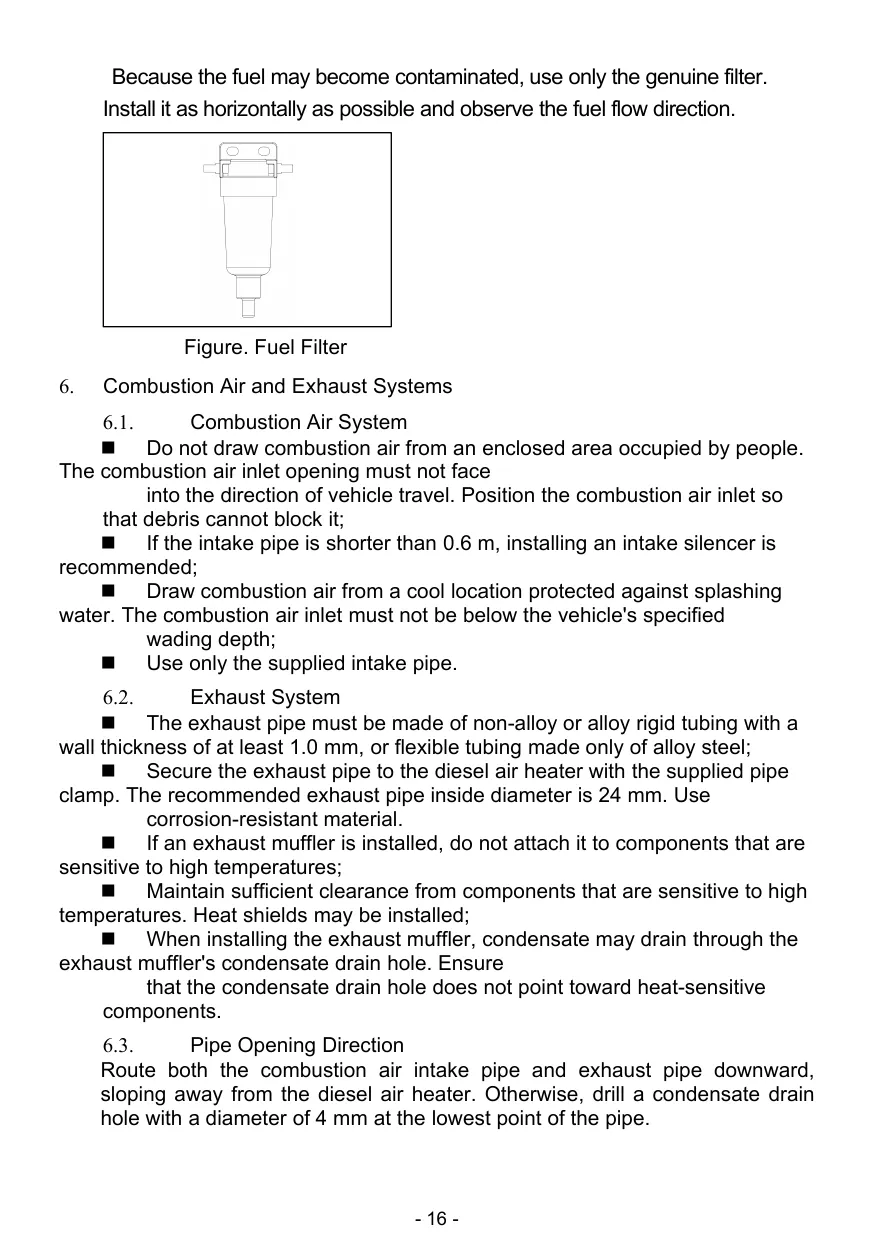
Use only the genuine fuel filter; install it as horizontally as possible, observing flow direction. Fuel Filter (manual p.16)
Do not draw combustion air from an enclosed area occupied by people. The inlet must not face the direction of travel and must be protected from debris. Draw air from a cool location protected from splashing water, above the specified wading depth. Use only the supplied intake pipe. An intake silencer is recommended if the pipe is shorter than 0.6 m.
Use exhaust pipe made of non-alloy or alloy rigid tubing at least 1.0 mm thick, or flexible tubing made only of alloy steel. Secure it with the supplied clamp; recommended inside diameter is 24 mm. Use corrosion-resistant material. Do not attach a muffler to heat-sensitive components; maintain clearance and use heat shields if needed. Ensure the muffler condensate drain hole does not point toward heat-sensitive components.
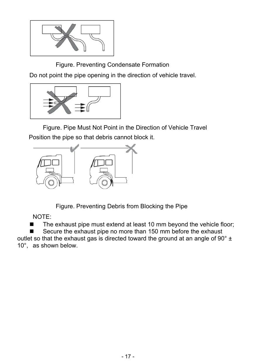
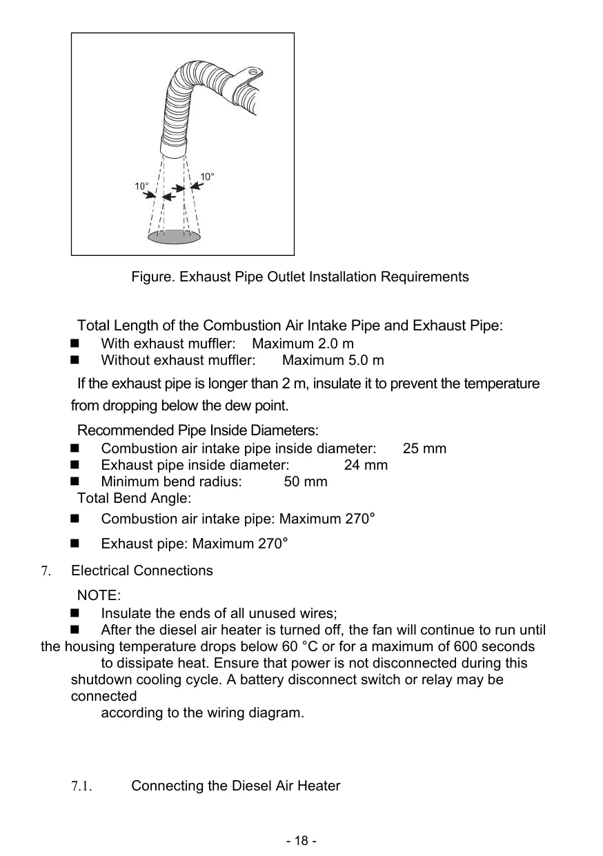
Route intake and exhaust pipes downward, sloping away from the heater; otherwise drill a 4 mm condensate drain hole at the lowest point. Do not point pipe openings in the direction of travel; prevent debris blocking them. The exhaust must extend at least 10 mm beyond the vehicle floor. Secure it no more than 150 mm before the outlet so exhaust points toward the ground at 90° ± 10°. Preventing Condensate Formation (manual p.17)See manual p.17 above.See manual p.17 above.Exhaust Outlet Installation (manual p.18)
Total intake and exhaust pipe length: maximum 2.0 m with muffler, 5.0 m without muffler. Insulate exhaust pipe longer than 2 m to prevent temperature falling below the dew point. Recommended inside diameters: intake 25 mm, exhaust 24 mm; minimum bend radius 50 mm; maximum total bend angle 270° for each pipe.
Insulate unused wire ends. Connect the power supply to the vehicle’s central electrical system and connect the control panel using the existing harness connector. After switch-off, the fan continues until housing temperature falls below 60 °C or for a maximum of 600 seconds; do not disconnect power during this cycle. A battery disconnect switch or relay may be connected according to the wiring diagram. See manual p.18 above.
The installation guide states that the exhaust surface is approximately 752°F (400°C). Keep flammable material away from the exhaust and muffler outlet and use insulation; never drill holes or install mechanical equipment on a wood floor. Do not use adhesives unable to withstand high temperatures, to prevent toxic fumes and fire. Leave 4 inches at the air inlet, keep the bottom exhaust pipe 2 inches above ground, and avoid excessive pipe length or bends. Do not let fuel enter the housing when filling; the manual says the fuel level should be near the tank opening. Do not block the intake pipe. For exhaust extensions, use the same or heat-resistant material, or heat-resistant stainless steel; keep total length within 2 meters, avoid sharp bends, route downward outdoors, and avoid multiple upward bends. Do not use non-heat-resistant rubber seals.
First start-up
In standby, press Settings five times in succession to start manual fuel priming. The display counts down from a maximum of 200 seconds.
When fuel reaches the glow plug, the heater ignites and starts automatically. Press any button to stop priming early; the heater may continue running briefly after priming stops, which the manual says is normal.
To start heating from standby, press and hold ON/OFF. Allow 3–5 minutes for normal operation and heat output. A small amount of initial white smoke can be normal after factory testing.
Operating the heater
The display indicates Eco, Standard, Boost, and Auto modes; preheating, operation, shutdown cooling, faults, ignition, timer, fuel pump and fuel level, glow plug, both blowers, signal, altitude, ambient and housing temperature, temperature units, operating parameters, blower speeds, voltage, and voice prompt language.
Start: In standby, hold ON/OFF.
Shut down: Hold ON/OFF until “OFF” appears. Do not operate the button during shutdown; wait for cooling and successful shutdown. NOTICE: Never forcibly disconnect power during shutdown. Otherwise heat cannot dissipate completely and substantial smoke will be produced on restart. If this occurs, wait until fuel inside has burned completely before resuming normal operation.
Mode: Press M to cycle Boost, Standard, Eco, and Auto.
Power: Press Fan Speed + or −. Eco supports levels 1–9, Standard 4–9, Boost 7–9.
Auto temperature: Default 21 °C; use Temperature + or − to select 10–45 °C. The set temperature is saved in Auto mode.
Parameters: While on, Settings cycles pump frequency, glow-plug power, altitude, total operating time, time until scheduled shutdown, and time until scheduled startup. The main screen returns after 20 seconds or a button press.
Units: While on, hold M for 3 seconds to switch Celsius/Fahrenheit; leave the chosen unit displayed 5 seconds to confirm. Range: 10–45 °C / 50–113 °F. The setting survives power disconnection.
Operating time: Automatically counts while on, up to 9999 minutes, then resets to zero. It is not retained when power is disconnected.
Timer: In standby, hold Timer for 2 seconds to schedule startup; while on, hold it for 2 seconds to schedule shutdown. Use Fan Speed + or − to choose 5, 10, 20, or 30 minutes; each subsequent press adjusts by 30 minutes up to 24 hours. Leave displayed for 5 seconds to confirm; set to 0 to cancel. The display colon flashes when enabled.
Voice prompts: While on, hold Settings for 3 seconds, then press Settings to cycle English, French, German, Italian, Spanish, Polish, Dutch, Swedish, or off. Leave the choice for 5 seconds to confirm. English is the default; the setting survives power disconnection. Prompts cover startup, shutdown, and fault codes.
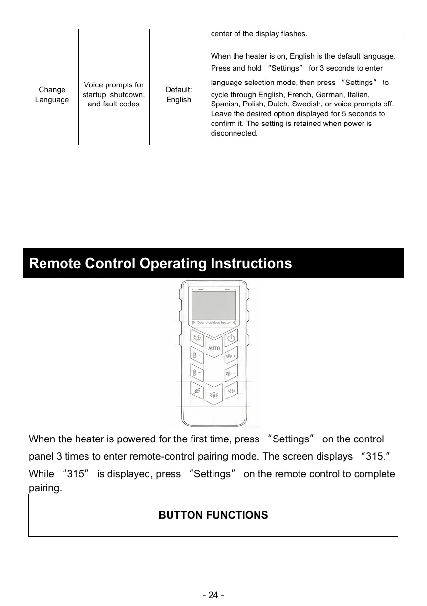
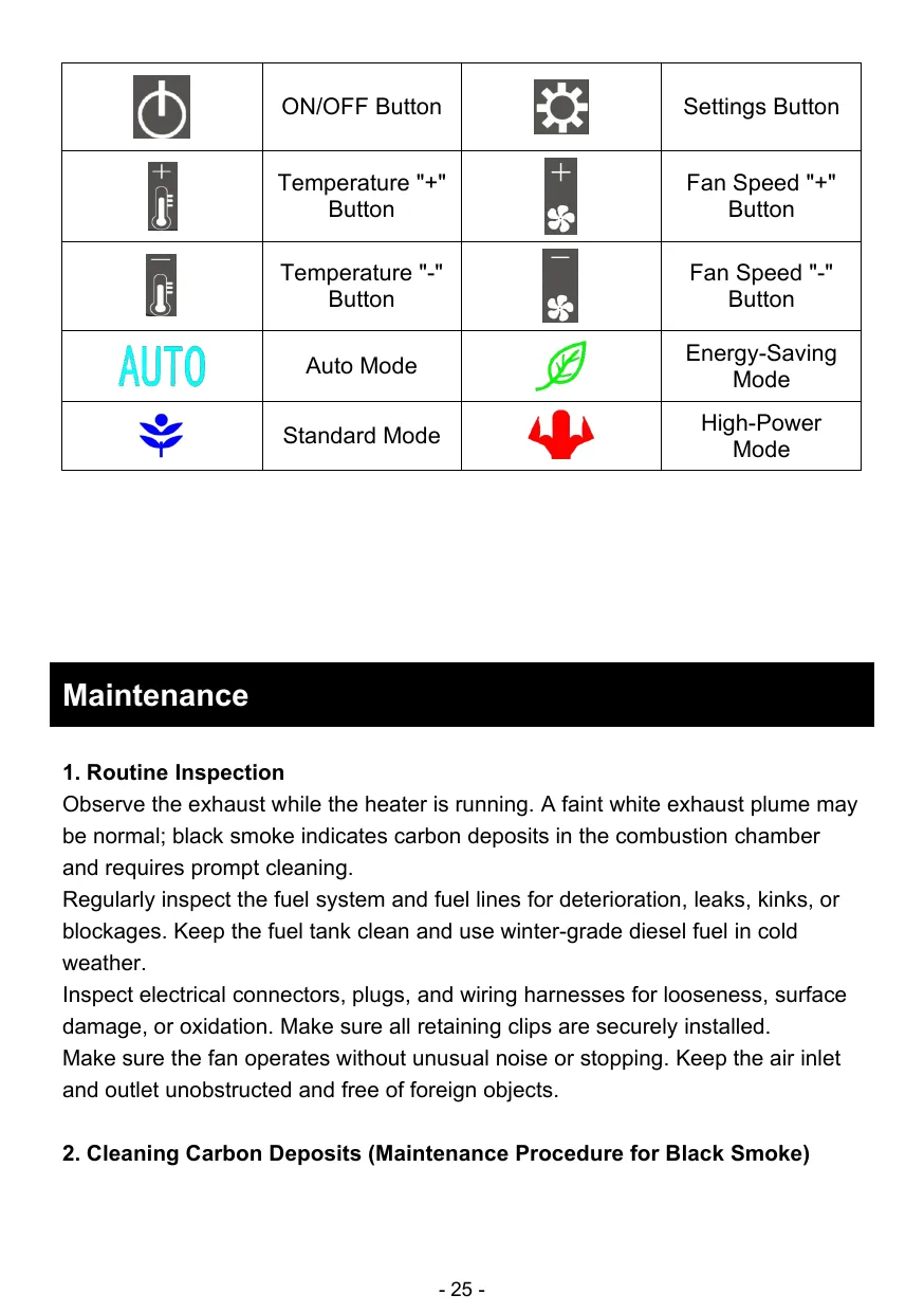
Remote: On first connection of power, press Settings on the control panel three times. When “315” appears, press Settings on the remote to pair. The remote has ON/OFF, Settings, Temperature +/−, Fan Speed +/−, Auto, Energy-Saving, Standard, and High-Power buttons. Remote Control Buttons (manual p.24, p.25)
The first code is printed as E-01 in the table and referenced as E-01 on p.30–31. All other table codes are printed without a hyphen.
Code
Meaning
What to do
E-01
Power Supply Voltage Too High
Check supply and terminal voltage. If over 32V, adjust the abnormal supply voltage. If supply is normal, replace controller.
E02
Power Supply Voltage Too Low
Check source: 12 V or 24 V DC, at least 15 A and rated power at least 150 W; minimum startup voltage 9 V for 12 V, 18 V for 24 V. Use a suitable adapter, battery pack, converter, or equivalent. Avoid makeshift battery-to-wiring clamps or fasteners. For harness extensions use at least 2 mm² conductors. If still inoperative, measure voltage and current at both source and heater-harness terminals.
E03
Fuel Metering Pump Open Circuit
Check pump connector for damage or displaced terminals and harness for broken wires. Check plug for looseness; disconnect and reinstall. If none applies, replace pump.
E04
Fuel metering pump short circuit
Check for pinched wiring and damaged insulation causing a short. If no short, replace pump; if unresolved, replace controller.
E05
Glow plug open circuit
Check connector is fully seated and not loose. If seated, remove and inspect plug for damage; replace if damaged. If operating normally, replace controller.
E06
Glow plug short circuit
Check wiring insulation and protective sleeves on center and side electrodes at the base for damage causing a short. If no short, check plug for damage. If operating normally, replace controller.
E07
Abnormal hot-air blower speed
Check unit is securely fastened and properly installed; check blower rubbing against housing. If unobstructed, replace motor assembly.
E08
Hot-air blower short circuit
Check for pinched wiring and damaged insulation; if intact, inspect connector housing and motor interior. If normal, replace controller.
E09
Diesel air heater flameout
Check for air in fuel line and continuous flow; check line for damage and leaks; check for an empty tank.
E10
Ignition failure
Check fuel in line. If combustion is present but code remains, inspect flame sensor and replace if damaged. If ignition does not occur, blow compressed air through intake and exhaust openings, thoroughly clean combustion chamber, and restart.
E11
Overheat Warning
Sensor activates protection when aluminum housing surface reaches or exceeds 295 °C. Check inlet duct, hot-air outlet duct, and exhaust pipe for bends or excessive length restricting exhaust flow and heat dissipation.
E12
Temperature sensor open circuit
Check connector is fully seated; check wiring for open circuit. If no problem, replace sensor; if fault remains, replace controller.
E13
Temperature sensor short circuit
Check wiring insulation and short circuit. If no damage or short, replace sensor; if fault remains, replace controller.
E14
Communication lost
Check blue control-panel communication wire for damage and connector terminals for looseness. If normal, replace panel; if fault remains, replace controller.
E15
Air inlet temperature too high
Check ambient temperature around control panel. If fault remains below 65 °C, replace panel.
E16
Abnormal combustion blower speed
Check whether impeller contacts combustion chamber U-shaped rubber plug/asbestos gasket, stopping or disturbing motor. If unobstructed, replace motor assembly.
E17
Combustion blower short circuit
Check for pinched wiring and damaged insulation. If intact, inspect connector housing and motor interior; if normal, replace controller.
E18
Combustion blower open circuit
Check connector is fully seated, then harness for broken wires. If none, replace motor assembly; if unresolved, replace controller.
E19
Hot-air blower open circuit
Check connector is fully seated, then harness for broken wires. If none, replace motor assembly; if unresolved, replace controller.
E20
Combustion blower circuit fault
Replace controller.
E21
Hot-air blower circuit fault
Replace controller.
Other troubleshooting guidance in the PDF:
White smoke / excessive manual priming: Excess fuel prevents ignition. Prime the fuel inlet, then stop. If too much fuel was added, disconnect the fuel line and restart 2–3 times; reconnect after normal operation returns. Alternatively, blow air continuously into the fuel inlet line with a hair dryer until normal operation returns. For unexpected power loss, use the Power Switch Button; wait for “OFF,” shutdown, and a complete fan stop before disconnecting power. Do not operate this button during the shutdown process. See E-01/E-02.
Black smoke: Check whether altitude exceeds the calibrated range, inspect the combustion-air intake and clearance for blockage, and check E-01/E-02 voltage/current. Inspect the combustion chamber for carbon and replace if necessary.
Blue smoke: Use only high-grade, fresh diesel, not blended diesel or other fuels; in winter use low-temperature-rated diesel.
Fuel leak: Inspect tank outlet and line for damage or cracks; avoid spilling fuel on the housing. Do not install on the side; face combustion-air inlet and exhaust outlet downward. Poor fuel may clog the glow-plug atomizing screen and allow mixture to leak through the exhaust; replace the screen and use high-grade diesel.
No fuel delivery or heat: Check for a kinked or bent fuel line.
Fuel from exhaust: Excess priming can fill the chamber and flow out of the exhaust. Follow the PDF’s fuel-line disconnection/restart or hair-dryer instructions above. Remove and inspect the glow-plug atomizing screen; clean or replace if blocked. The PDF also lists abnormal voltage as a cause.
Fuel from combustion-air intake: Excess priming can fill the chamber and flow out of the intake. Stop priming; if excessive, disconnect fuel line and restart 2–3 times, then reconnect after normal operation. Alternatively, blow air continuously into the combustion-air intake pipe with a hair dryer until normal operation returns. Do not mount on the side; face intake and exhaust downward.
Exhaust glows red: Shut down immediately; remove aluminum housing and check whether the combustion chamber is sealed, or replace the chamber.
Abnormal noise: Shut down immediately and inspect exhaust pipe, muffler, and outlet for blockage; remove blockage before resuming.
Diesel odor: Use high-quality, fresh diesel, not blended or other fuels; use low-temperature diesel in winter. Remove housing and inspect for fuel leaks; replace affected parts promptly.
Plastic odor: Use heat-resistant accessories; avoid excessively long or bent tubing. Exhaust can reach approximately 752°F. Never drill an installation hole through a wood floor or use non-heat-resistant rubber seals; odors and poisoning may result.
Smoke or insufficient heat after operation: Clean or replace the carbon-loaded combustion chamber promptly.
Blown fuse: Remove and inspect fuse; replace if damaged. Check positive and negative terminals for a short; if shorted and the main control board is damaged, replace it.
Maintenance & storage
Run the heater for approximately 10 minutes every four weeks to prevent mechanical parts seizing. At the start of winter replace summer diesel with winter-grade fuel, then run at full power for 20 minutes.
Under normal conditions the manual says no routine maintenance is required; have a trained technician inspect at least at the beginning of each heating season. After 3,000 operating hours or 3 years, check inlet/outlet for dirt and foreign objects, clean the exterior without letting water in, check electrical connectors for corrosion and secure connections, inspect exhaust and combustion-air pipes for damage and blockage, replace the fuel filter if installed, and check line and filter for leaks.
WARNING: Keep the intake grille clean and unobstructed; do not cover it with clothing or other items. After turning off heat, allow approximately 3–10 minutes for the fan to stop; do not disconnect power until cooling is complete and the fan has stopped. When the panel turns off, the unit is fully shut down. Keep exhaust unobstructed and away from flammable materials and goods on the ground. Install exhaust horizontally or sloping downward, never vertically upward.
Observe exhaust during operation: faint white exhaust may be normal; black smoke indicates chamber carbon deposits requiring prompt cleaning. Regularly inspect fuel system and lines for deterioration, leaks, kinks, and blockage; keep the tank clean and use winter-grade diesel in cold weather. Check connectors, plugs, harnesses, retaining clips, fan noise and operation, and clean, unobstructed inlets/outlets.
To clean carbon deposits: turn off, disconnect power, and wait until completely cool; remove housing; use a hex key to remove main control board mounting bolts; remove four fan assembly bolts; remove four combustion chamber bolts and the chamber; clean deposits, replacing the entire chamber assembly if buildup is severe; reinstall in reverse order and tighten all bolts; reconnect power and test-run.
Annually or at the start of each heating season, remove carbon and debris from the combustion chamber, exhaust, and combustion-air intake. From the second year, inspect carbon deposits and fuel-filter element; replace fuel filter and glow plug as necessary. For long-term storage, drain residual diesel from fuel lines, disconnect power, and store in a dry, dust-free location.
Regulatory notices
This device complies with Part 15 of the FCC Rules. Operation is subject to the following two conditions: (1) This device may not cause harmful interference; and (2) this device must accept any interference received, including interference that may cause undesired operation.